It's done, it works, it was fun! [Summary Report]
“Wait, we’re missing the routes for the LED!”
We are planning to mill two shield pcb’s for the huzzah32 controller, and we started with the simpler one (“input-shield”) that will house connections for the buttons and LED (the other one will have the dc-dc converter and signaling for the servo, but will be fashioned later on our spare time and is outside of this course). The pcb work started with a logical layout in Eagle based on our TinkerCad model. When we had the initial logical model, we then laid out the components physically to the board on the board view. After doing that, we ran the Eagles autorouting function to get the routing done on the physical layout and we were beaming with delight as it managed to wrestle out a fully connected layout. We were almost taking this straight to the milling-machine, but fortunately had the sense to step through each route only to find that we had omitted a couple of connections. We added them dutifully but then ran in to problems with the autoroute function. The routing was simply impossible with the given physical layout, and to achieve full connectivity we had to make some further adjustments. With some fiddling of the components we managed to free just enough space for the algorithm to barely squeeze out a single fully connected solution, and even though it was not the prettiest, we took it to the bank.
The milling process had it’s kinks also. In the first draft we did not drill the lanes deep enough, and in the cut out phase the board slipped free off the base and the drill head took it for a walk. The second attempt was a fail also, but the third one yielded us with a beautiful board!
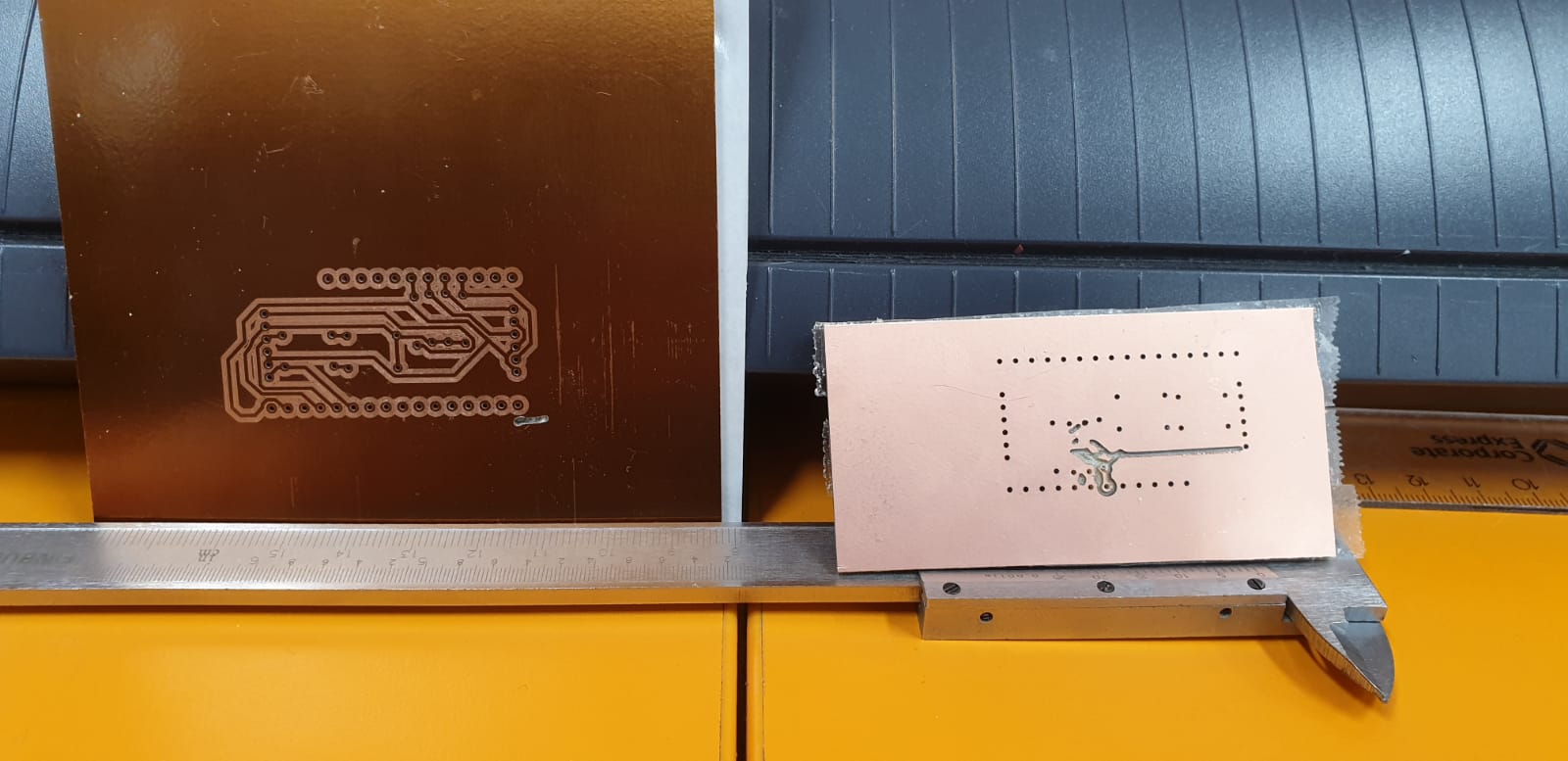 Fig. 1: The two failed pcbs
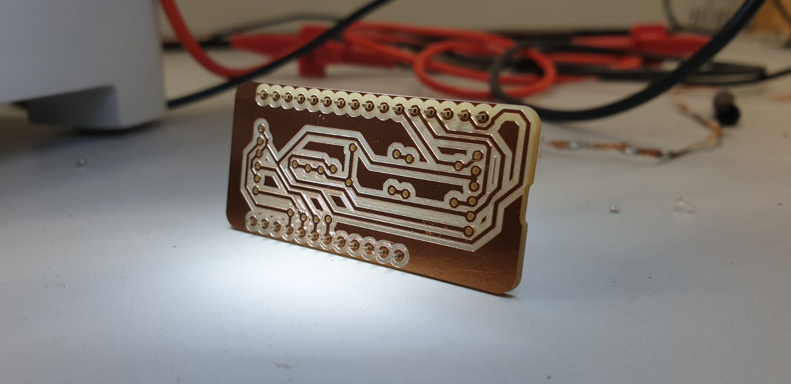 Fig. 2: The success pcb front/up
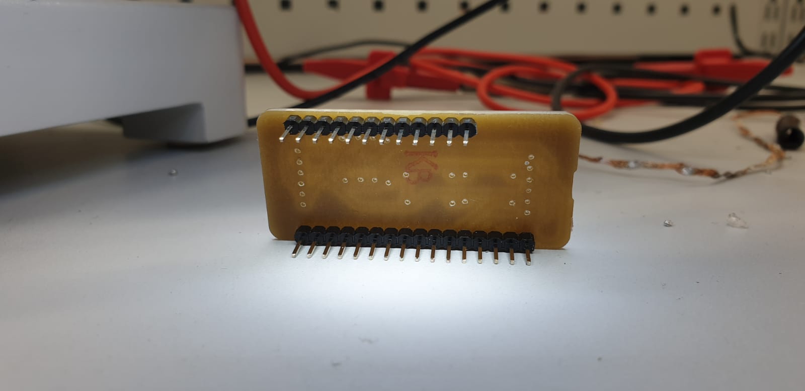 Fig. 3: The success pcb back/down with pins attached
 Fig. 4: The success pcb back/down with resistors soldered
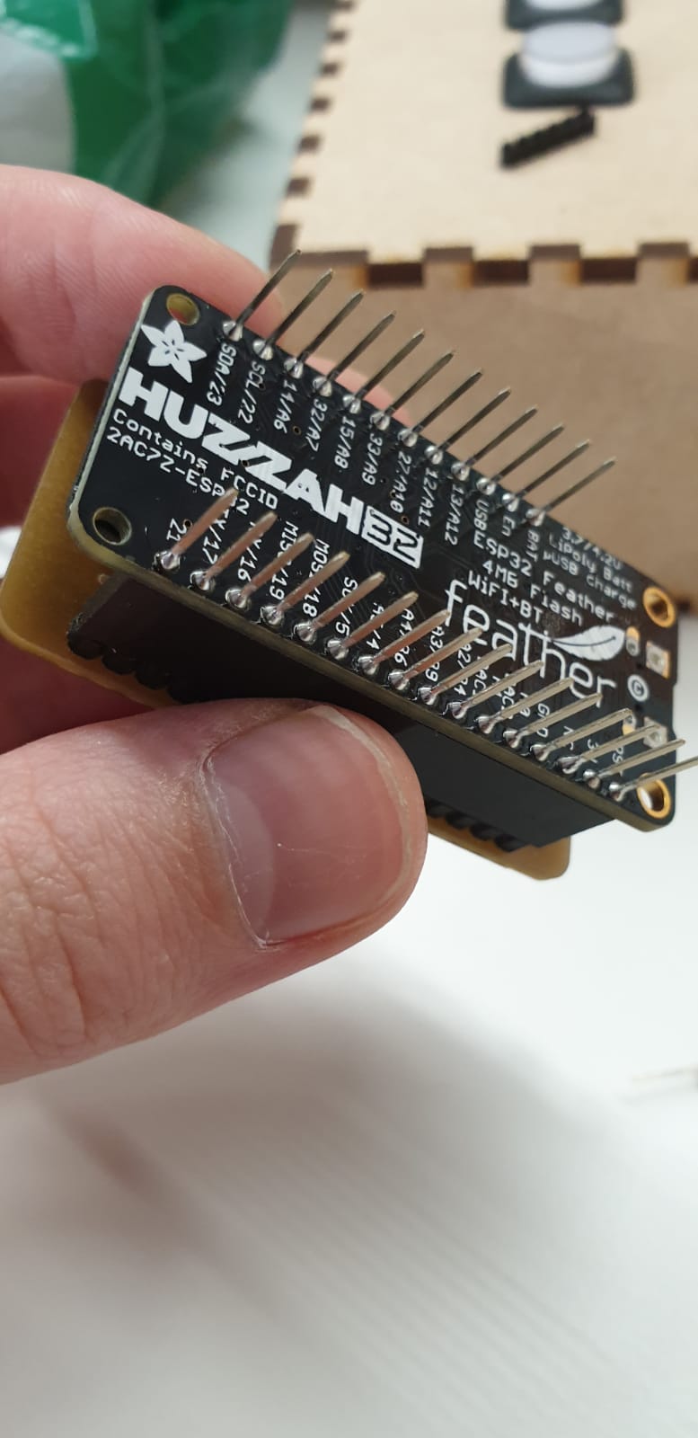 Fig. 5: The pcb shield (“input-shield”) attached to the huzzah32
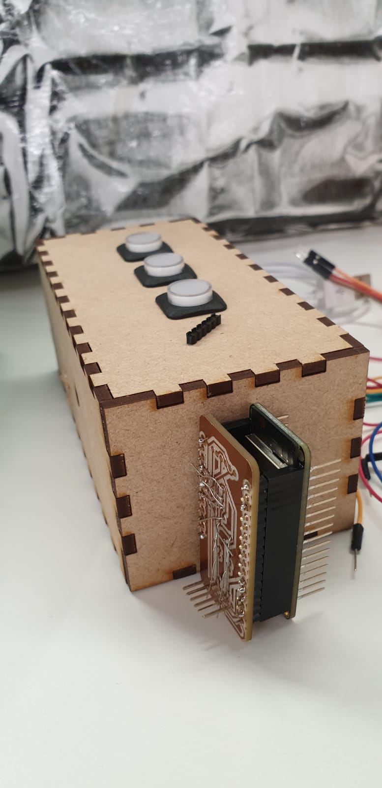 Fig. 6: Form factor comparison with the prototype mdf chassis
Division of work
We did not specifically named any team members for each part of work we conducted over the period of this course. We worked as a team of four for the vast majority of all time used to work on this project. In order to give some idea of the roles we all had during this project, the following list gives you an idea where we all had our own main focus. However, again, most of the time we worked together as a team and the list is not meant to be read as a strict work division document:
- Jouni Pikkarainen
- Steered the idea of the automated blinds project
- Prior investment on many tools and components, ordered missing parts required for the build
- Kept the “end user requirements” in mind based on the wanted use case with non destructive design
- Worked a lot on designing and logically implementing the input shield
- Joni Rajala
- Design and implementation of MDF based components such as the window frame, controller box and box holder
- Major investment in providing the arduino code running on the huzzah32
- Ville Friman
- Major influence on problem solving on all ends
- Special interest in preparing for future and taking into account possibilities of extending the capabilities of the device
- Major investment in providing the arduino code running on the huzzah32
- Steered focus and kept the idea of ens user product clear in our minds
- Janne Koskenniemi
- Keeping it real by realizing and sharpening what matters the most
- Wrote many of the amazing blog posts and kept everyone posted on real deadlines
- Extra bonus on taken safety measures, even provided a fire blanket!
The end results
As of writing this, the pcb shield is still not yet fully ready, as it is missing the buttons and the led, but we are confident to have them in place and in operation next week. There is still a possibility that we have to remill the board, as the pads for the pin components that we used in Eagle that will provide the wire connectivity for the buttons and the led were smaller than the pins we had. But we are confident either way that we continue to progrees on this endeavor.
During the course we learned a bunch of things. We’ve successfully build a device that tilts the blind mechanism based on the current level of luminosity. We are very happy with the results, and we are still continuing the work to minimize the electronics and to literally fabricate a proper casing for the apparatus. In the scope of this course we did multitude of things, and to remind you of all of our doings, here is a list of all components of the design we’ve done (in the order they were pretty much implemented):
- TinkerCad model of the controller, actuator (servo motor) and sensors with other required components
- Arduino code runnable on the real device used and on the TinkerCad model
- Blinds frame to hold the actual blinds for presentation and testing purposes
- Blinds controller box to hold the breadboard, buttons and sensors in place for mid term presentation
- Blinds controller box holder to hold attach the controller box to the blinds frame
- Dc-dc converter schematic design (“servo-shield”) to provide 5V and control signal for the high torque servo motor used on the build
- Schematic and board design for the input shield and the actual implementation of the shield, provides interface for all the inputs and logically controlled power to the LED indicating the automagic mode
Resources
Even though many of the components and resources have been already hyperlinked, here is an explicit list of links to resources generated and/or used during this course:
- digital-fabrication organization used for storing all resources during this course on GitHub. You can find everything we’ve done navigating from here.
- digital-fabrication.github.io blog (this blog) repository
- blinds repository containing code, schematics and other source and binary files used for fabricating
Other meaningful more direct links (that are also on the repositories):
- Presentation slides
- Blinds control box
- Blinds frame
- Blinds servo-shield schematic
- Blinds input-shield
- Blinds controller box holder
- Blinds controller source code
To all readers
If you’ve reached this far on this blog posts and even if you’ve also read our earlier blog posts, we would like to thank you for taking interest in our project. We’ve learned a lot during this course and hope that you’ve learned something new as well, or at least now know more of the possible pitfalls of designing electronic devices.
Thank y’all
We would like to thank all course personnel and the working forces of Fab Lab Oulu for your support on our journey to design and implement the automagic blinds.
- Special thanks to Erno Lang and Peetu Virkkala for the words of encouragement and the ironing out the very first problems encountered during the proof of concept build!
- Special thanks to Dr. Antti Mäntyniemi for providing extra help on dc-dc converter design and other very aspects of the project along the way!