SmartsPlind Planning phase Team Team [Introductory Report]
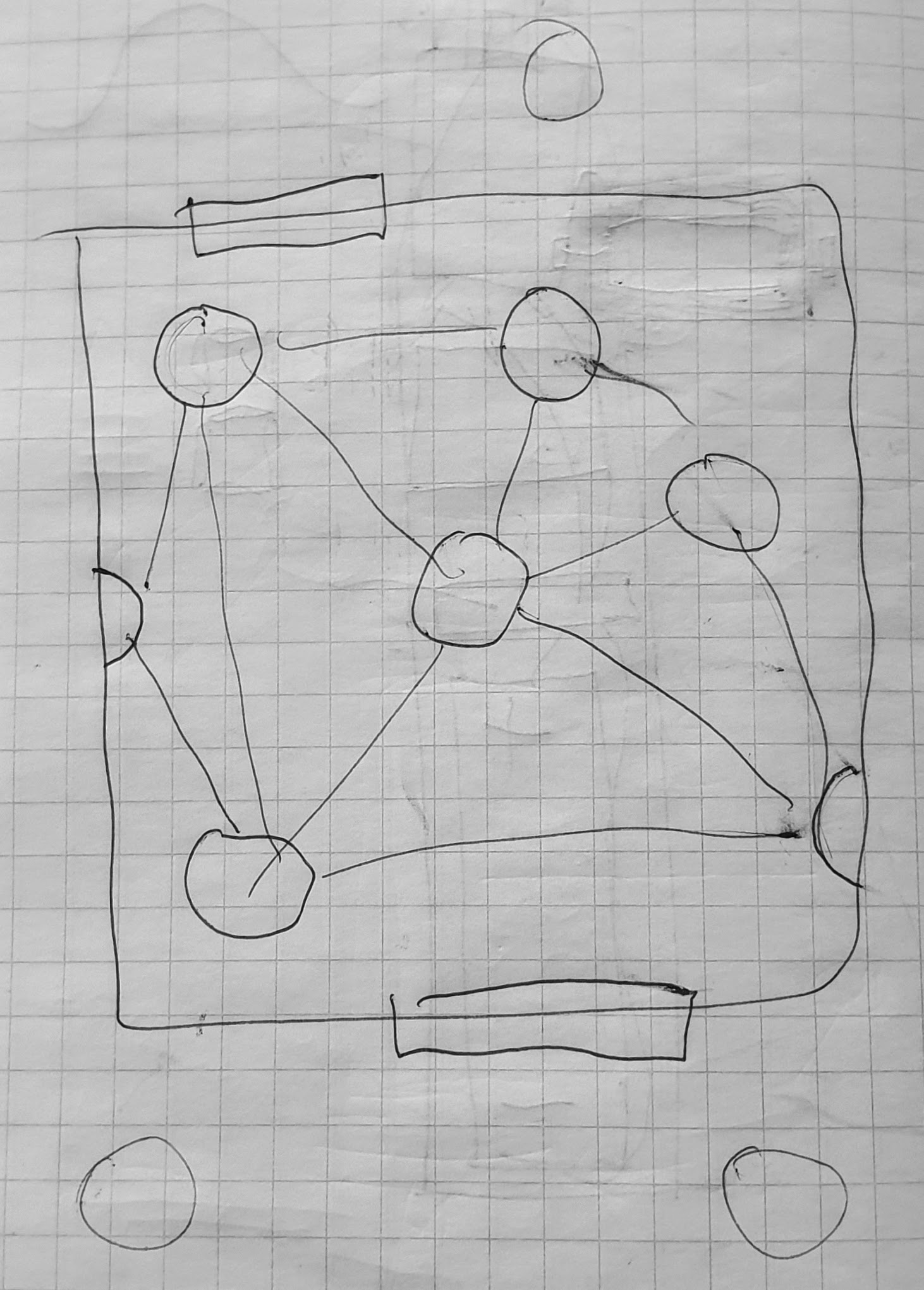
Our initial project plan was set by one our team member already having built a partly working venetian blinds tilt mechanism controller, and so he steamrolled all our other ideas. In the development planning phase we quickly coalesced into an IOT type self adjusting blind fed by wireless luminosity measurements from an ad-hoc network forming group of measurement nodes. But with realizing the available time and resources and the possible work entailed in fully realizing the initial far flung plan of, we have toned down the scope, to a single device with the sensors, actuators and control and power supply unit.
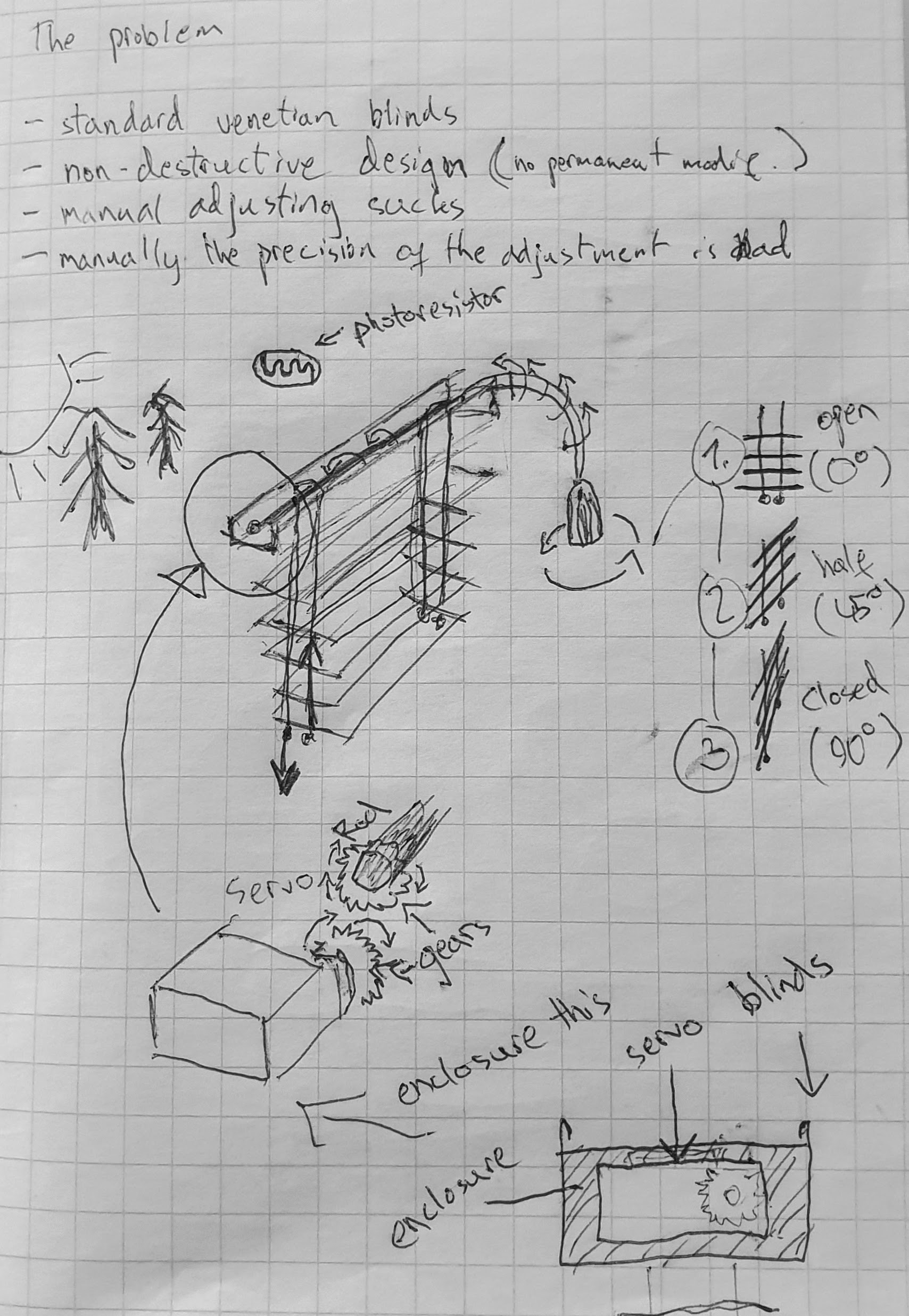
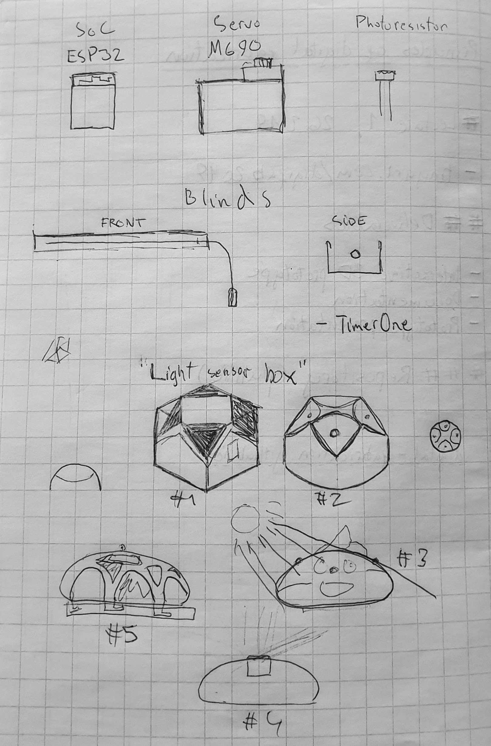
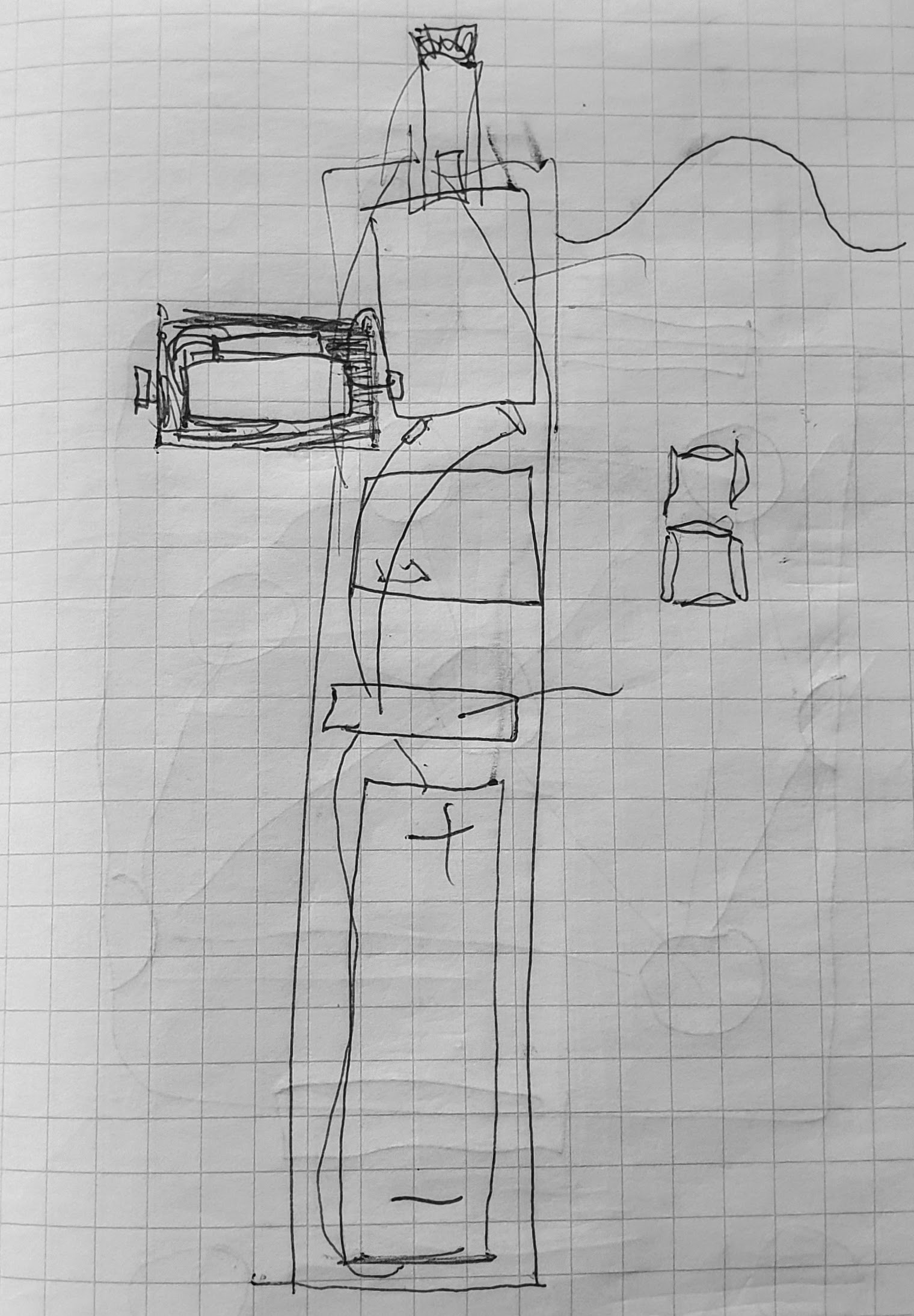
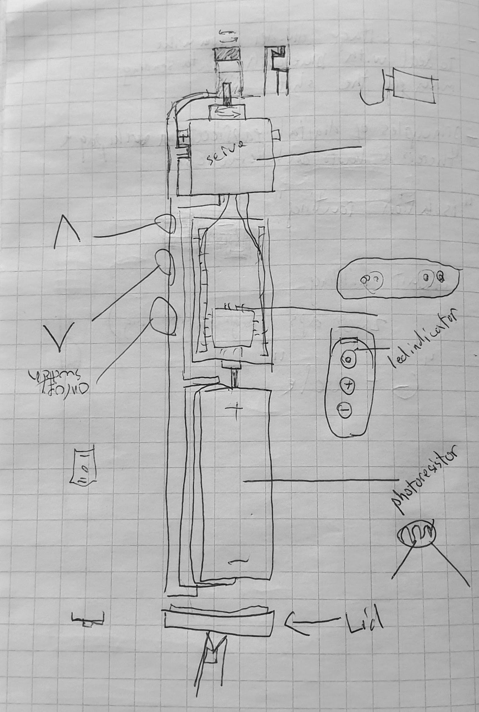
The blinds manipulator unit in the already working prototype was fitted into the blinds top casing, but we came up a with an external mountable version design. This design was partly influenced by an already available commercial product. The device will contain an adapter that fits into a standard blinds tilting rod, so that it can be installed and moved to blinds that contain this shutter mechanism which seems to be standardized mechanism. The device will also contain the servo to drive the tilt, an integrated light sensor, a controller board and a power supply. The device is meant to operate on the sensor readings, but we are planning to install buttons for manual operation as a fail-safe plan to deliver some input in case the sensor plan does not pan out.
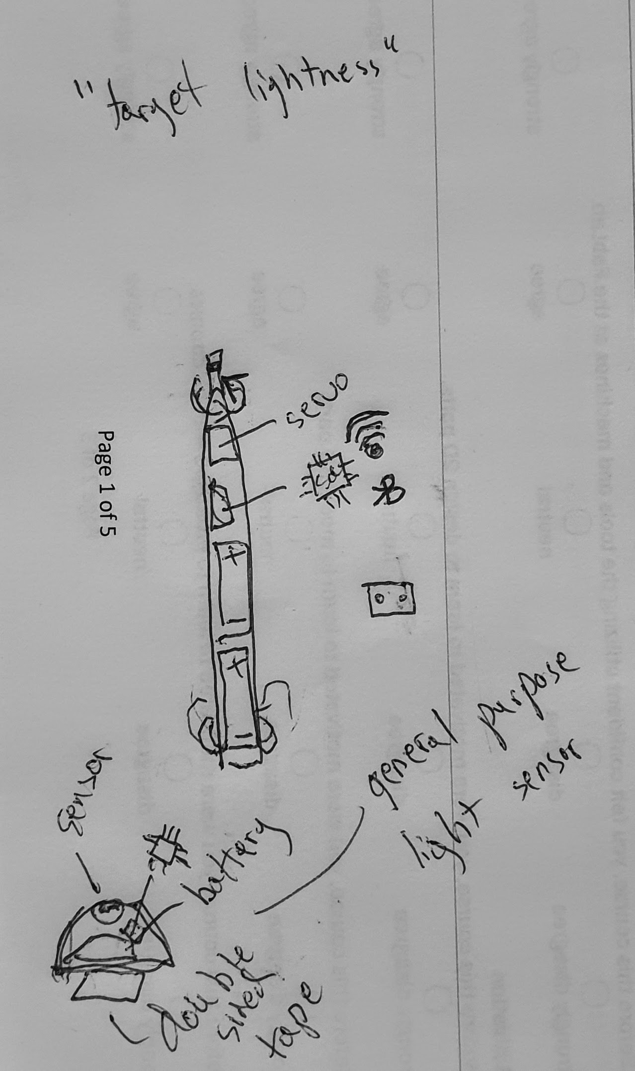
Open design questions currently include the torque capacity requirement for the servo (will the driver be powerful enough to manipulate the tilting rod?), the power supply unit (PSU capacity versus consumption of the fully implemented unit), safety (board power handling, servo messing up digits).
Initial build that were created before the principles of digital fabrication course.